
I have a card file box which has been converted into a small ballot box. I needed a locking mechanism for it but didn’t want anything added to the outside of the box. I didn’t want any visible sign on the outside that the box was locked in order to preserve it’s original appearance.
I was inspired by the Most Useless Machine EVER! which appeared on the Instructables website. This project used a 555 Timer to driver a RC servo to toggle a switch. I thought it would be great if I could take the concept and package inside my box and drive the latching mechanism with a RC servo. Because all the circuitry would be inside the box and the box would be locked when the lid was closed, I wanted the power supply to be isolated from the control circuit to prevent the batteries from going flat too fast.
This is the circuit I came up with.
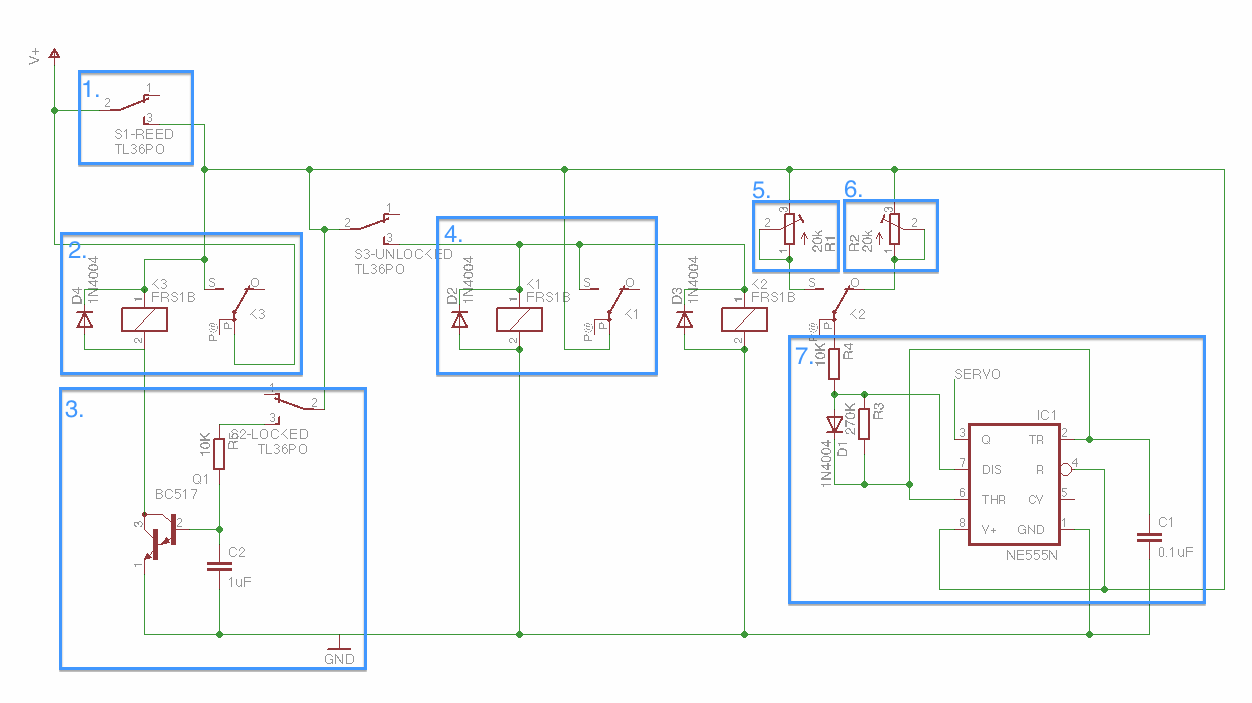
Secret box circuit.
The servo is driven by the 555 timer in 7. and the open and closed positions are control by 20 turn variable resistors in 5. (closed position) and 6. (open position). This gives fine control over the open and closed positions. These variable resistors are selected by a relay.
At rest, the servo is in the closed position and the switch S2-LOCKED in 3. is open.
The circuit powered by closing the magnetic reed switch S1-REED with a magnet. The servo moves towards the open position and closes switch S2-LOCKED. The darlington transistor Q1 in 3. is triggered, switching on and allowing the relay in 2. to energise and latch on. Capacitor C2 also starts charging.
When the servo reaches the open position the switch S3-UNLOCKED is closed. This energises the relay in 4. which latches on and supplies power to the direction select relay. The servo now moves towards the closed position and switch S2-UNLOCKED is open.
When the servo reaches the closed position the switch S2-LOCKED is opened. Capacitor C2 discharges through the darlington Q1 in 3. keeping the main relay in 2. energised. When the voltage of capacitor C2 drops below the trigger threshold of the darlington, the darlington switches off and the relay de-energises, removing power from the batteries. The circuit returns to it’s initial state and is idle.
The delay created by the capacitor discharging through the darlington provides enough time for the servo to reach the closed position without overshooting.
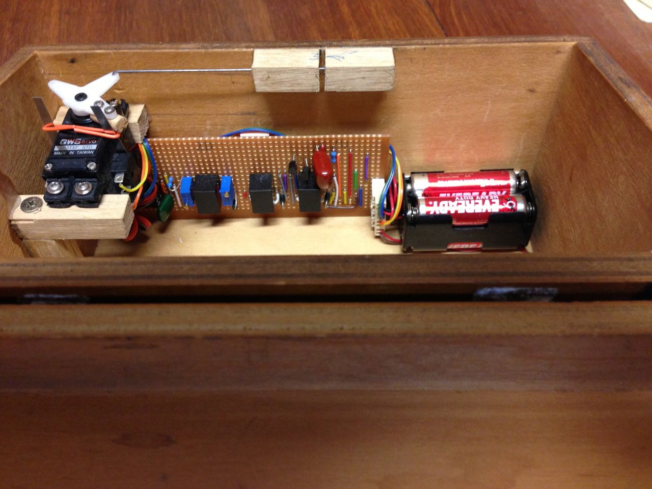
The circuit was built on stripboard and installed into the box.
-
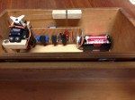
- Servo, circuit board, batteries.
-
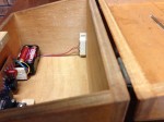
- Batteries, reed switch.

As a programmer, this project would have been easier to design and implement with an Arduino. The Arduino would have needed to be continually powered to detect the open request via the reed switch and there is a danger that the batteries would go flat seizing the mechanism. In this case the low-tech solution is a better fit to the design requirements.